Estamos a traduzir a nossa loja para português!
Mas como temos muitos produtos e páginas, vai demorar algum tempo. Entretanto, o nosso catálogo de produtos estará em inglês. Obrigado pela sua paciência!
- Allowable Torque Range(N•m)
- Shaft Bore Dia. 1 d1 (or d)(mm)
- 4
- 5
- 6
- 6.35
- 7
- 8
- 9.53
- 10
- 11
- 12
- 14
- 15
- 16
- 18
- 20
- Shaft Bore Dia. 2 d2 (or d)(mm)
- 4
- 5
- 6
- 6.35
- 7
- 8
- 9.53
- 10
- 11
- 12
- 14
- 15
- 16
- 18
- 20
- O.D. D(mm)
- 14.5
- 16.8
- 20
- 26
- 30
- 34
- 38
- Overall Length(mm)
- 18.4
- 24.4
- 27.2
- 30.4
- 33
- 34
- 39.5
- Max. Rotational Speed Range(r/min)
- Allowable Torque(Nm)
- 3
- 5
- 7
- 10
- 30
- 32
- 50
- Max. Rotational Speed(r/min)
- 4000
- 5000
- 6000
- 7000
- 8000
- Allowable Lateral Misalignment(mm)
- 0.5
- 0.8
- 1
- Shaft I.D. d1 Change Hole Dia. [LDC] Specified in 0.1mm Increment[4-20/0.1]
- Shaft I.D. d2 Change Hole Dia. [RDC] Specified in 0.1mm Increment[4-20/0.1]
- CAD
- 2D
- 3D
- Dias de envio estimados
- Tudo
- Dentro de 7 dias úteis
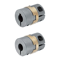
Oldham couplings / hub clamping, feather key / 1 disc: aluminium bronze / body: stainless steel

Passe o rato sobre a imagem para a aumentar
Número da peça:
candidatos encontrados.Desenho de contorno e tabela de especificações
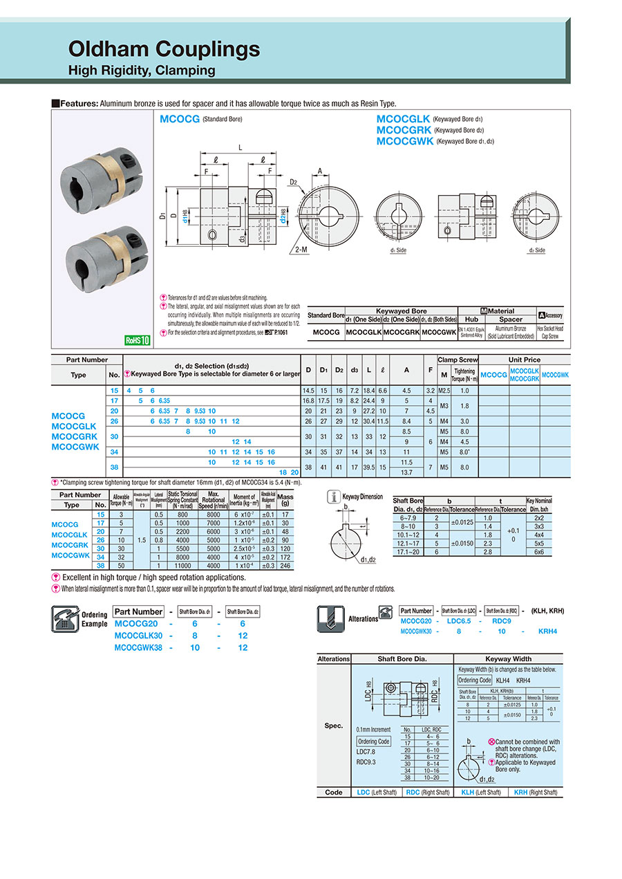
Dimensional Drawing
MCOCG (Standard Bore)
MCOCGLK (Keywayed Bore d1)
MCOCGRK (Keywayed Bore d2)
MCOCGWK (Keywayed Bore d1, d2)
d1 side
d2 side


| Shaft bore diameter d1, d2 | b | t | Key Nominal Dim. (b x h) | ||
| Standard Dimensions | Tolerance | Standard Dimensions | Tolerance | ||
| 6 to 7.9 | 2 | ±0.0125 | 1.0 | +0.10 0 | 2 × 2 |
| 8 to 10 | 3 | 1.4 | 3 × 3 | ||
| 10.1 to 12 | 4 | ±0.015 | 1.8 | 4 × 4 | |
| 12.1 to 17 | 5 | 2.3 | 5 × 5 | ||
| 17.1 to 22 | 6 | 2.8 | 6 × 6 | ||
| 22.1 to 30 | 8 | ±0.018 | 3.3 | +0.20 0 | 8 × 7 |
| 30.1 to 32 | 10 | 10 × 8 | |||
[ ! ] Recommended Fit Tolerance of Applicable Shaft Diameter: h8.
[ ! ] The lateral, angular, and axial misalignment values shown are for each occurring individually. When multiple misalignments are occurring simultaneously, the allowable maximum value of each will be reduced to 1/2.
[ ! ] Shaft Insertion Depth should be ℓ (hub) length.
| Standard Bore | Keywayed Bore | [M] Material | [S] Surface Treatment | Operating Temp. Range °C | ||||
| d1 (One Side) | d2 (One Side) | d1, d2 (Both Sides) | Hub | Spacer | Hex Socket Head Cap Screw | Hex Socket Head Cap Screw | ||
| MCOCG | MCOCGLK | MCOCGRK | MCOCGWK | EN 1.4301 Equiv. (Sintered) | Aluminum Bronze (Solid Lubricant Embedded) | EN 1.7220 Equiv. | Black Oxide Film | -50 to 200 |
[ ! ] Spacers are not sold as single items.
Specification Table
| Part Number | — | Shaft Bore Dia. d1 | — | Shaft Bore Dia. d2 |
| MCOCG20 | — | 6 | — | 6 |
| MCOCGLK30 | — | 8 | — | 12 |
| MCOCGWK38 | — | 10 | — | 12 |
| Part Number | d1, d2 Selection (However, d1 ≤ d2) [ ! ] Hole Dia. 6 or more is available for Keywayed Bore | D | D1 | D2 | d3 | L | ℓ | A | F | Clamp Screw | ||||||||||||||||
| Type | No. | M | Tightening Torque (N⋅m) | |||||||||||||||||||||||
| MCOCG MCOCGLK MCOCGRK MCOCGWK | 15 | 4 | 5 | 6 | 14.5 | 15 | 16 | 7.2 | 18.4 | 6.6 | 4.5 | 3.2 | M2.5 | 1.0 | ||||||||||||
| 17 | 5 | 6 | 6.35 | 16.8 | 17.5 | 19 | 8.2 | 24.4 | 9 | 5 | 4 | M3 | 1.8 | |||||||||||||
| 20 | 6 | 6.35 | 7 | 8 | 9.53 | 10 | 20 | 21 | 23 | 9 | 27.2 | 10 | 7 | 4.5 | ||||||||||||
| 26 | 6 | 6.35 | 7 | 8 | 9.53 | 10 | 11 | 12 | 26 | 27 | 29 | 12 | 30.4 | 11.5 | 8.4 | 5 | M4 | 3.0 | ||||||||
| 30 | 8 | 10 | 30 | 31 | 32 | 13 | 33 | 12 | 8.5 | 6 | M5 | 8.0 | ||||||||||||||
| 12 | 14 | 9 | M4 | 4.5 | ||||||||||||||||||||||
| 34 | 10 | 11 | 12 | 14 | 15 | 16 | 34 | 35 | 37 | 14 | 34 | 13 | 11 | M5 | 8.0* | |||||||||||
| 38 | 10 | 12 | 14 | 15 | 16 | 38 | 41 | 41 | 17 | 39.5 | 15 | 11.5 | 7 | M5 | 8.0 | |||||||||||
| 18 | 20 | 13.7 | ||||||||||||||||||||||||
[ ! ] *Clamping screw tightening torque for shaft diameter 16mm (d1, d2) of MCOCG34 is 5.4 (N·m).
| Part Number | Allowable Torque (N⋅m) | Allowable Angular Misalignment (°) | Allowable Lateral Misalignment (mm) | Static Torsional Spring Constant (N·m/rad) | Max. Rotational Speed (r/min) | Moment of Inertia (kg⋅m2) | Allowable Axial Misalignment (mm) | Mass (g) | |
| Type | No. | ||||||||
| MCOCG MCOCGLK MCOCGRK MCOCGWK | 15 | 3 | 1.5 | 0.5 | 800 | 8000 | 6 ×10⁻⁷ | ±0.1 | 17 |
| 17 | 5 | 0.5 | 1000 | 7000 | 1.2 × 10⁻⁶ | ±0.1 | 30 | ||
| 20 | 7 | 0.5 | 2200 | 6000 | 3 ×10⁻⁶ | ±0.1 | 48 | ||
| 26 | 10 | 0.8 | 4000 | 5000 | 1 ×10⁻⁵ | ±0.2 | 90 | ||
| 30 | 30 | 1 | 5500 | 5000 | 2.5 × 10⁻⁵ | ±0.3 | 120 | ||
| 34 | 32 | 1 | 8000 | 4000 | 4 ×10⁻⁵ | ±0.2 | 172 | ||
| 38 | 50 | 1 | 11000 | 4000 | 1 ×10⁻⁴ | ±0.3 | 246 | ||
[ ! ] When lateral misalignment is more than 0.1, spacer wear will be in proportion to the amount of load torque, lateral misalignment, and rotational speed.
[ ! ] The moment of inertia is the magnitude of the rotatory inertia of a coupling. The higher this value increases, the larger rotatory inertia becomes.
(Used for motor selection)
Alterations
Alterations | Shaft Bore Dia. | Keyway Width | |||||||||||||||||||||||||||||||||||||||
Code | LDC(Left Shaft) | RDC(Right Shaft) | KLH(Left Shaft) | KRH(Right Shaft) | |||||||||||||||||||||||||||||||||||||
Spec. | Ordering Example LDC7.8 RDC9.3  ■LDC and RDC Specifiable Range (0.1 mm Increments)
| Ordering Example KLH4 KRH4 
[ ! ]Only shaft bore diameters 8, 10 and 12 can be specified [ ! ]Applicable to Keywayed Bore only. | |||||||||||||||||||||||||||||||||||||||
●: Selectable -: Not Selectable Not Possible: Not Available
Part Number | Shaft Bore Dia. | Keyway Width | |||
Hole Type | Type | LDC | RDC | KLH | KRH |
d1(Left) | d2(Right) | d1(Left) | d2(Right) | ||
Standard Bore | MCOCG | ● | ● | Not Possible | |
ー | ● | ||||
● | ー | ||||
ー | ー | ||||
Keywayed Bore d1(Left) | MCOCGLK | ● | ● | ー | Not Possible |
ー | ● | ● | |||
● | ー | ー | |||
ー | ー | ● | |||
Keywayed Bore d2(Right) | MCOCGRK | ● | ● | Not Possible | ー |
ー | ● | ー | |||
● | ー | ● | |||
ー | ー | ● | |||
Keywayed Bore d1, d2 (Right and Left) | MCOCGWK | ● | ● | ー | ー |
ー | ● | ● | ー | ||
● | ー | ー | ● | ||
ー | ー | ● | ● | ||
Coupling Selection and Handling
(1) Select Coupling Type
Simplified Selection Table
Coupling Characteristics | Motor | |||||
Type | Zero Backlash | High Torque | Allowable Lateral Misalignment Allowable Angular Misalignment | Servo | Stepping Motor Compact Servo | General Purpose |
Disc type | ◎ | ◎ | 〇 | ◎ | 〇 | × |
Oldham type | × | ◎ | ◎ | × | × | ◎ |
Slit type | ◎ | 〇 | 〇 | 〇 | ◎ | × |
●Connection with Servo Motors / Stepping Motors (For motion control)
Calculate the Compensation Torque by multiplying Compensation Factor with the Motor's Peak Torque.
*For Compensation Factor, please see product specifications in the product page.
Choose a coupling with the torque capacity (shaft slip torque) higher than the calculated compensation torque.
Compensation Torque = Motor's Peak Torque × Compensation Factor
● Connection with General-purpose Motor (For power transmission)
※* Calculate the load torque, and the compensation torque should be 1 to 5 times of the load torque.
Choose a coupling with the torque capacity (shaft slip torque) higher than the calculated compensation torque.
Load Torque(N・m)=9550× Transmission Power(kW) Rotational Speed (r/min)
Compensation Torque = Load Torque (N⋅m) × 1 to 5
(3) Check coupling tolerance
Check that the Tolerance (Angular and Lateral misalignments and Max. Rotational Speed)
and Max. Rotational Speed) and the Moment of Inertia mentioned in the catalogue meet the conditions of the device.
(4) Select shaft bore
Check if the outer diameter of the connecting shaft is included in the inner diameter range of the coupling.
If the outer diameter is not included, select a larger size.
(5) Select shaft connection method
Select in accordance with the clamp, keyed locking, keyless clamping applications.
(6) Final confirmation
Finally check the dimension table to confirm that the coupling is compatible with the device.
Lista de números de peça
| Número da peça |
|---|
Preço unitário (excluindo IVA)(Preço unitário incluindo IVA) | Data de envio standard |
|---|
- ( - ) | 7 dias úteis |
- ( - ) | 7 dias úteis |
- ( - ) | 7 dias úteis |
- ( - ) | 7 dias úteis |
- ( - ) | 7 dias úteis |
- ( - ) | 7 dias úteis |
- ( - ) | 7 dias úteis |
- ( - ) | 7 dias úteis |
- ( - ) | 7 dias úteis |
- ( - ) | 7 dias úteis |
- ( - ) | 7 dias úteis |
- ( - ) | 7 dias úteis |
- ( - ) | 7 dias úteis |
- ( - ) | 7 dias úteis |
- ( - ) | 7 dias úteis |
- ( - ) | 7 dias úteis |
- ( - ) | 7 dias úteis |
- ( - ) | 7 dias úteis |
- ( - ) | 7 dias úteis |
- ( - ) | 7 dias úteis |
- ( - ) | 7 dias úteis |
- ( - ) | 7 dias úteis |
- ( - ) | 7 dias úteis |
- ( - ) | 7 dias úteis |
- ( - ) | 7 dias úteis |
- ( - ) | 7 dias úteis |
- ( - ) | 7 dias úteis |
- ( - ) | 7 dias úteis |
- ( - ) | 7 dias úteis |
- ( - ) | 7 dias úteis |
- ( - ) | 7 dias úteis |
- ( - ) | 7 dias úteis |
- ( - ) | 7 dias úteis |
- ( - ) | 7 dias úteis |
- ( - ) | 7 dias úteis |
- ( - ) | 7 dias úteis |
- ( - ) | 7 dias úteis |
- ( - ) | 7 dias úteis |
- ( - ) | 7 dias úteis |
- ( - ) | 7 dias úteis |
- ( - ) | 7 dias úteis |
- ( - ) | 7 dias úteis |
- ( - ) | 7 dias úteis |
- ( - ) | 7 dias úteis |
- ( - ) | 7 dias úteis |
- ( - ) | 7 dias úteis |
- ( - ) | 7 dias úteis |
- ( - ) | 7 dias úteis |
- ( - ) | 7 dias úteis |
- ( - ) | 7 dias úteis |
- ( - ) | 7 dias úteis |
- ( - ) | 7 dias úteis |
- ( - ) | 7 dias úteis |
- ( - ) | 7 dias úteis |
- ( - ) | 7 dias úteis |
- ( - ) | 7 dias úteis |
- ( - ) | 7 dias úteis |
- ( - ) | 7 dias úteis |
- ( - ) | 7 dias úteis |
- ( - ) | 7 dias úteis |
Informações detalhadas
Informações básicas
Contorno e especificações
General Information - Claw Couplings
Shaft Coupling Selection Details
- Material: aluminum, aluminum alloy, steel, stainless steel, plastic
- Coupling buffer material: polyacetal, polyurethane, nylon, aluminum bronze, carbon fibre reinforced polymer (CFRP)
- Disc material: stainless steel, polyimide, carbon fibre (carbon)
- Fastening: hub clamping, half shell clamping, threaded pin clamping, clamping sleeve, keyway
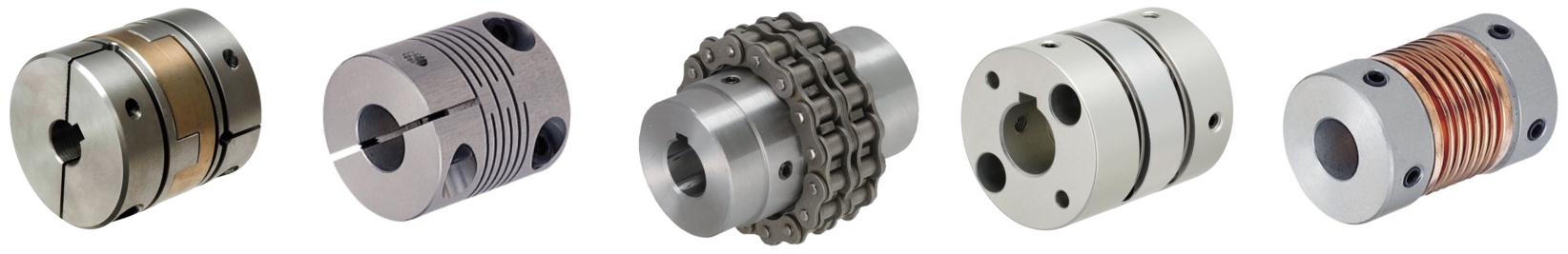
- Design: slit coupling, disc coupling (servo coupling), Oldham coupling, dog coupling, jaw coupling, bellow coupling, metal bellow coupling, elastomer coupling
- ISO tolerances: H8
- Shaft diameter: 1 to 45 mm
- Outer diameter: 6 to 95 mm
- Length: 8.4 to 100 mm
- Offset: angle offset, radial offset, axial offset
Design Overview
Description/Basics
A shaft coupling, also called a compensating coupling, is generally used for the transmission of torque for mechanical engineering. Flexible shaft couplings (non-rigid) can compensate for lateral, axial and angular offsets (misalignment). Therefore, these are common connecting elements between motors and axles/shafts or even ball screws.
There are various types of designs, such as the jaw couplings, disc couplings (servo couplings), slit couplings, bellow couplings, Oldham couplings and many others, which are selected depending on the type of misalignment. You can determine which design is the right one for transmission in your application with the Coupling Selection Method available as a PDF.
When the shaft coupling is professionally installed, the transmission of rotational forces should be slip-free. To do this, the appropriate shaft coupling must be selected depending on the application. Here, it is important to observe the degree of misalignment, the maximum speed of rotation and the permissible torque of the compensation coupling and not to exceed these values during operation. If several misalignments occur at the same time, it is recommended to reduce the maximum value of the specified misalignment by approximately half.
The most commonly used elastomer coupling is the jaw coupling, which consists of a plastic buffer with damping properties. As a result, shocks and vibrations in a drive system can be damped, which protects adjacent components in the transmission of force. Our product range offers you alternative materials for the elastomers. These include among others aluminum bronze and carbon fibre-reinforced plastic.
The different shaft connections on the compensation couplings allow various connection variants for assembly. For this purpose, hub clamping, half shell clamping, slot clamping, threaded pin clamping, chip sleeve and keyways are available.
If a keyway is selected for a MISUMI shaft coupling, it is recommended obtaining the MISUMI machine key, as it is best to combine these.
A shaft coupling can be used for precise positioning. These are often combined together with slide screws or ball screws. A disc clutch (servo coupling) is suitable for this application, since it has a high torsional rigidity.
In addition to the standardized diameter of the shaft bore, MISUMI offers the option LDC and RDC, which allows the drill diameter to be adjusted to the shaft end in 0.1 mm increments.
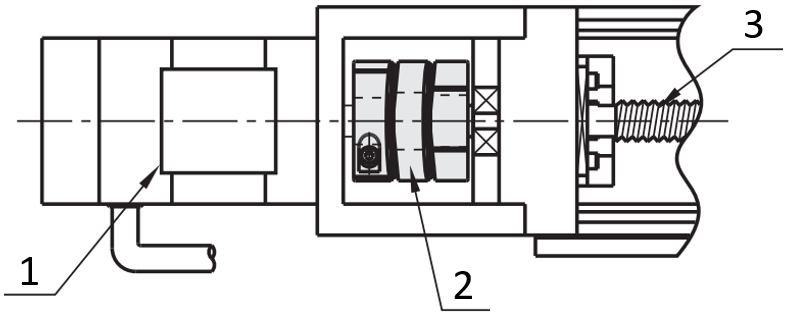
Application Examples - Claw Couplings
Shaft coupling with servo motor and ball screw
(1) Servo motor, (2) disc coupling (servo coupling), (3) ball screw

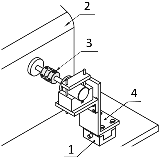
Slit coupling with encoder
(1) Bearing with housing, (2) shaft coupling, (3) motor, (4) axles/shafts
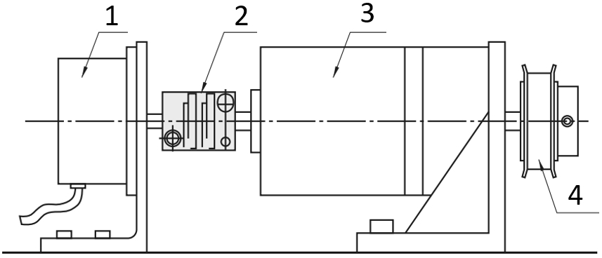
Engine test stand with Oldham coupling
(1) X-axis positioning stage, (2) performance test station, (3) shaft coupling, (4) brackets, L-shaped
Shaft coupling with motor and gearbox
(1) Motor, (2) Shaft coupling, (3) Conversion/Reducing gears, (4) Timing pulleys / Idlers
Industrial Applications