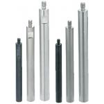
Round rod spacers / stainless steel, steel / Treatment selectable / external thread, internal thread / Wrench flat (Part Numbers - CAD Download)

- Order quantities extended (D-JIT)
(i)Remark
- The area around the wrench flats may become glossy due to deburring (buffing).
Part Number
Once your search is narrowed to one product,
the corresponding part number is displayed here.
- Drawing / Specifications
- 3D Preview 3D preview is available after complete configuration
- Part Numbers
- Catalog
Dimensional Drawing
| L Dimension | L Dimension Tolerance |
| 15 ≤ L ≤ 300 | ±0.1 |
| 300 < L ≤ 600 | ±0.3 |
| 600 < L ≤ 1000 | ±0.4 |

[ ! ]The dimension tolerance for L, S, SC, ℓ1 conforms to JIS B 0405 Class m.
 | M | MC | g |
2 | 1.5 | 0.8 | |
2.6 | 2.1 | ||
3 | 2.4 | 1 | |
4 | 3.2 | 1.2 | |
5 | 4.1 | 1.5 | |
6 | 4.4 | 2 | |
8 | 6 | 3 | |
10 | 7.7 | ||
12 | 9.4 | 4 | |
16 | 13 | ||
20 | 16.4 | 5 | |
24 | 19.6 | ||
27 | 23 | ||
30 | 25 |
* C0.2 to 0.5 at the corner
[ ! ] Trivalent Chromate (Black), Clear/Black Anodize may not always be fully deposited on threaded studs or internal tapped threads.
* D tolerance of trivalent chromate (black) is ±0.05.
[ ! ] Due to the thickness of the plating, the threaded studs of Trivalent Chromate (black) products may not pass through the ring gauge, but they can be used in general-purpose threaded holes (formerly JIS Class 2).
[ ! ] SC ≤ L - ℓ1
[ ! ] Tapping may cause slight swelling of D dimension.
[ ! ]Anti-rust Oil is applied on SS400 equivalent products.
[ ! ] The area around the wrench flats may become glossy due to deburring (buffing).
| Type | [M] Material | [S] Surface Treatment | ||||
| L Dimension Selectable | L Dimension Configurable | |||||
| Standard | Wrench Flats | Thread Dia. Configurable | Thread Dia. Configurable, Wrench Flats | |||
| — | NETGRF | NETGRS | NETG | NETGS | EN 1.0038 Equiv. | — |
| ETKGR | ETKGRF | ETKGRS | ETKG | ETKGS | Black Oxide | |
| PETGR | PETGRF | PETGRS | PETG | PETGS | Electroless Nickel Plating | |
| — | BETGRF | BETGRS | BETG | BETGS | Trivalent Chromate (Black) | |
| SETGR | SETGRF | SETGRS | SETG | SETGS | EN 1.4301 Equiv. | — |
| — | AETGRF | AETGRS | AETG | AETGS | EN AW-2017-T4 Equiv. | Clear Anodize |
| — | ABETGRF | ABETGRS | ABETG | ABETGS | Black Anodize | |
(Reference Value)
Aluminum | EN 1.0038 Equiv.·EN 1.4301 Equiv. | |
M | Recommended torque | Recommended torque |
(0.5T series) | (T series) | |
3 | 0.315 | 0.63 |
4 | 0.75 | 1.5 |
5 | 1.5 | 3 |
6 | 2.6 | 5.2 |
8 | 6.2 | 13 |
10 | 12.2 | 25 |
12 | 21 | 42 |
16 | 53 | 106 |
Specification Table
| Part Number | — | L | — | SC | — | M | — | N |
| ETKGR10 ETKGRF6 ETKG12 ETKGS20 | — — — — | 150 32 250 400 | — | SC100 | — — | M6 M8 | — — | N8 N10 |
| Part Number | L Selection | M (Coarse) | S | W | ℓ1 | |||||||||||||||||||
| Type | D | |||||||||||||||||||||||
| EN 1.0038 Equiv. ETKGR PETGR EN 1.4301 Equiv. SETGR | 6 | 15 | 20 | 25 | 30 | 35 | 40 | 45 | 50 | 3 | 3.5 | 5 | 8 | |||||||||||
| 8 | 20 | 25 | 30 | 35 | 40 | 45 | 50 | 60 | 70 | 80 | 90 | 100 | 110 | 120 | 130 | 140 | 150 | 4 | 6 | 7 | ||||
| 10 | 20 | 25 | 30 | 35 | 40 | 45 | 50 | 60 | 70 | 80 | 90 | 100 | 110 | 120 | 130 | 140 | 150 | 200 | 5 | 6 | 8 | |||
| 12 | 25 | 30 | 35 | 40 | 45 | 50 | 60 | 70 | 80 | 90 | 100 | 110 | 120 | 130 | 140 | 150 | 200 | 6 | 7.5 | 10 | 10 | |||
| 15 | 30 | 35 | 40 | 45 | 50 | 60 | 70 | 80 | 90 | 100 | 110 | 120 | 130 | 140 | 150 | 200 | 8 | 10 | 13 | |||||
| 20 | 40 | 45 | 50 | 60 | 70 | 80 | 90 | 100 | 110 | 120 | 130 | 140 | 150 | 200 | 10 | 15 | 17 | |||||||
| Part Number | L 0.1 mm Increments * D = 5, 35, 40, 50 is 0.5 mm increments | SC 0.5 mm Increments [ ! ] For Wrench Flats Type only | M (Coarse) | W | ℓ1 | ||
| Type | D | ||||||
| L Dimension Configurable EN 1.0038 Equiv. NETGRF ETKGRF PETGRF BETGRF (D ≤ 30) EN 1.4301 Equiv. SETGRF (D ≤ 30) EN AW−2017 Equiv. AETGRF (6 ≤ D ≤ 20) ABETGRF (6 ≤ D ≤ 20,Y ≤ 500) | L Dimension Configurable, Wrench Flats EN 1.0038 Equiv. NETGRS ETKGRS PETGRS BETGRS (D ≤ 30) EN 1.4301 Equiv. SETGRS (D ≤ 30) EN AW−2017 Equiv. AETGRS (6 ≤ D ≤ 20) ABETGRS (6 ≤ D ≤ 20,Y ≤ 500) | * 5 | 15.0 to 100.0 | 0 to 92.0 | 2.6 | 4 | 8 |
| 6 | 15.0 to 290.0 | 0 to 282.0 | 3 | 5 | |||
| 8 | 20.0 to 390.0 | 0 to 382.0 | 4 | 7 | |||
| 10 | 20.0 to 580.0 (492.5) | 0 to 572.0 (484.5) | 5 | 8 | |||
| 12 | 25.0 to 680.0 (491.0) | 0 to 670.0 (481.0) | 6 | 10 | 10 | ||
| 15 | 30.0 to 780.0 (488.0) | 0 to 770.0 (478.0) | 8 | 13 | |||
| 20 | 35.0 to 770.0 (485.0) | 0 to 760.0 (475.0) | 10 | 17 | |||
| 25 | 45.0 to 870.0 | 0 to 860.0 | 12 | 22 | |||
| 30 | 55.0 to 960.0 | 0 to 945.0 | 16 | 27 | 15 | ||
| * 35 | 55.0 to 900.0 | 0 to 885.0 | 16 | 30 | |||
| * 40 | 65.0 to 1000.0 | 0 to 980.0 | 20 | 36 | 20 | ||
| * 50 | 80.0 to 1000.0 | 0 to 980.0 | 24 | 41 | |||
| Part Number | L 0.1 mm Increments * D = 5, 35, 40, 50 is 0.5 mm increments | SC 0.5 mm Increments [ ! ] For Wrench Flats Type only | M (Coarse) Selection | N (Coarse) Selection | W | ℓ1 | ||||||||||||||||||||||
| Type | D | |||||||||||||||||||||||||||
| Thread Dia. Configurable EN 1.0038 Equiv. NETG ETKG PETG BETG(D ≤ 30) EN 1.4301 Equiv. SETG (D ≤ 30) EN AW−2017 Equiv. AETG (6 ≤ D ≤ 20) ABETG (6 ≤ D ≤ 20,Y ≤ 500) | Thread Dia. Configurable, Wrench Flats EN 1.0038 Equiv. NETGS ETKGS PETGS BETGS (D ≤ 30) EN 1.4301 Equiv. SETGS (D ≤ 30) EN AW−2017 Equiv. AETGS (6 ≤ D ≤ 20) ABETGS (6 ≤ D ≤ 20,Y ≤ 500) | * 5 | 15.0 to 100.0 | 0 to 92.0 | 2.6 | 3 | 4 | 2.6 | 3 | 4 | 8 | |||||||||||||||||
| 6 | 15.0 to 290.0 | 0 to 282.0 | 3 | 4 | 5 | 3 | 4 | 5 | ||||||||||||||||||||
| 8 | 20.0 to 390.0 | 0 to 382.0 | 3 | 4 | 5 | 6 | 3 | 4 | 5 | 7 | ||||||||||||||||||
| 10 | 20.0 to 580.0 (495.5) | 0 to 572.0 (487.5) | 3 | 4 | 5 | 6 | 8 | 3 | 4 | 5 | 6 | 8 | ||||||||||||||||
| 12 | 25.0 to 680.0 (494.0) | 0 to 670.0 (484.0) | 4 | 5 | 6 | 8 | 10 | 4 | 5 | 6 | 8 | 10 | 10 | |||||||||||||||
| 15 | 30.0 to 780.0 (492.5) | 0 to 770.0 (482.5) | 5 | 6 | 8 | 10 | 12 | 5 | 6 | 8 | 10 | 13 | ||||||||||||||||
| 20 | 40.0 to 770.0 (492.5) | 0 to 760.0 (482.5) | 5 | 6 | 8 | 10 | 12 | 16 | 5 | 6 | 8 | 10 | 12 | 17 | ||||||||||||||
| 25 | 55.0 to 870.0 | 0 to 860.0 | 5 | 6 | 8 | 10 | 12 | 16 | 20 | 5 | 6 | 8 | 10 | 12 | 16 | 22 | ||||||||||||
| 30 | 65.0 to 960.0 | 0 to 945.0 | 5 | 6 | 8 | 10 | 12 | 16 | 20 | 24 | 5 | 6 | 8 | 10 | 12 | 16 | 20 | 27 | 15 | |||||||||
| * 35 | 80.0 to 900.0 | 0 to 885.0 | 6 | 8 | 10 | 12 | 16 | 20 | 24 | 6 | 8 | 10 | 12 | 16 | 20 | 24 | 30 | |||||||||||
| * 40 | 80.0 to 1000.0 | 0 to 980.0 | 8 | 10 | 12 | 16 | 20 | 24 | 8 | 10 | 12 | 16 | 20 | 24 | 36 | 20 | ||||||||||||
| * 50 | 80.0 to 1000.0 | 0 to 980.0 | 10 | 12 | 16 | 20 | 24 | 10 | 12 | 16 | 20 | 24 | 41 | |||||||||||||||
Alterations
| Part Number | — | L | — | SC | — | M | — | N | — | (LKC·MLC·HL) | |
| ETKGRF10 ETKG12 ETKGS20 | — — — | 150 250.3 400 | — | SC100 | — — | M6 M8 | — — | N8 ND10 | — — — | MLC7.0 LKC LKC | − HL10 |
| Alterations | L Dimension Tolerance | Overall Length (L Dimension) Accuracy Revised | Effective Tapped Length | Threaded Length | Through Hole for Hex Wrench | |||||||||||||||||||||||||||||||||||||||
 |  |  |  |  | ||||||||||||||||||||||||||||||||||||||||
| Code | LKC | LVC | ND | MLC | HL | |||||||||||||||||||||||||||||||||||||||
| Spec. | L Dimension tolerances are as follows: Ordering Code LKC By specifying LKC, L dim. can be configured in 0.1 mm increments.
| When ordering multiple items, the variation in each L dimension will be made within ±0.02 mm. Ordering Code LVC [!]Applicable when L ≤ 200 and orders per line item is 20 pcs. or less [ NG ]Not applicable to L Dimension Selectable, Black Anodize | Changes the effective length of tapped part to J x 3. Ordering Code ND6 (N is changed to ND) [ ! ]ND × 4+2 ≤ L [ ! ] Applicable to Thread Dia. Configurable Type only [NG] Not applicable when N2.6 | Threaded Length [NG] Not applicable when D = 5 [ ! ] MLC = 0.1 mm Increments M × 1 ≤ MLC < M × 1.5 Ordering Code MLC10 [ ! ] Not Applicable to L Dimension Selectable Type | HL = 1 mm Increments Ordering Code HL10 [!] d/2 + 5 ≤ HL ≤ L- (d/2 + 5) [ ! ] Applicable when 8 ≤ D ≤ 30 only
When this Alteration is specified in combination with SC, a through hole is machined in perpendicular to the SC part. [NG] Not Applicable to L Dimension Selectable Type | |||||||||||||||||||||||||||||||||||||||
General Information - Hexagonal Rods

Selection details of spacers/spacers (hexagonal, square, cylindrical)
- Material: aluminum, steel, stainless steel, PMMA, PEEK
- Coatings: uncoated, burnished, chemically nickel-plated, anodized, chromated
- Basic shapes: hexagon, square, round
- End forms: straight, female thread, male thread, female thread with centering pin
- Outer diameter (round): 4 to 50 mm
- Spanner flat (hexagon, square): 4 to 32 mm
- Length: 5 to 800 mm
- Threads: M2 to M24
Description/Basics
Spacers are generally used as spacing connections. Due to their diversity, the wide range of design concepts can be realized with spacer bolts and practically every application can be realized using the appropriate spacer bolt.
The design and assembly of thin plates makes it extremely difficult to work with counterbores or internal threads. Therefore, spacer bolts are often used on plates, sheet metal or printed circuit boards (PCB).
The selectable assembly threads, the individually configurable length of the spacers, and the selectable length tolerance via the [LKC] option offer great design freedom compared to conventional mass-produced products. This advantage is particularly important if, for example, plates of different thicknesses or particularly thin plates are utilized.
For applications with particularly high positioning requirements, it is recommended to combine shim rings with a spacer. These can be configured in thicknesses from 0.01 to 1 mm and integrated as an additional compensating element.
The assembly of hexagonal spacers is particularly easy with the hex, since they can be held against one another with an open-ended spanner. With round spacer bolts, this can be realized with a spanner flat. The spacer bolts are also available with one-sided or two-sided internal thread (long nut). For precise positioning of a spacer bolt with an internal thread or external thread, MISUMI also offers a centering pin in the ISO tolerance h7.
This variety enables virtually barrier-free assembly of the components to be joined with screws, internal threads and external threads or nuts.
Application Examples - Hexagonal Rods

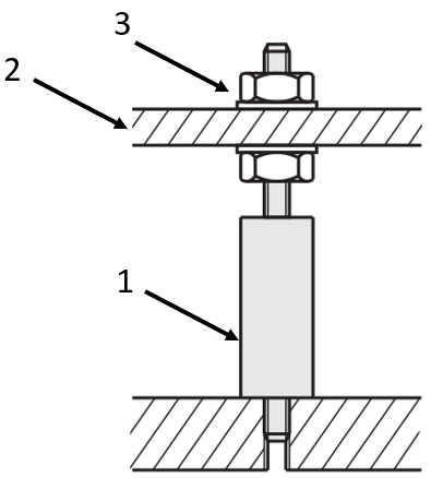
Application example: spacer bolt with external thread
(1) Spacer bolts with external thread on both sides, (2) mounting plate, (3) nut

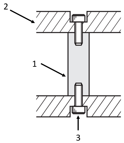
Application example: spacer bolts with internal thread
(1) Spacer with internal thread on both sides, (2) mounting plate, (3) screw

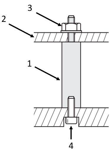
Application example: spacer with tappet
(1) Distance bolts with centering pin, (2) mounting plate, (3) nut, (4) screw

Application example: threaded spacer pin
(1) spacer bolts with internal thread and external thread, (2) mounting plate, (3) nut, (4) screw
Industrial Applications


Part Number:
- In order to open the 3D preview, the part number must be fixed.
3D preview is not available, because the part number has not yet been determined.
| Part Number |
Standard Unit Price
| Minimum order quantity | Volume Discount | RoHS | Characteristics/Applications | O.D. D (φ) | Length L (mm) | Material Details | Material | Surface Treatment | Thread Dia. M (mm) | Screw Dia. N (mm) | Distance to Wrench Slot S [SC] (mm) | Dimension Specifying | Wrench Flats | Effective Tapped Length (Nominal Dia. × 3) [ND] | |
|---|---|---|---|---|---|---|---|---|---|---|---|---|---|---|---|---|---|
- | 1 | 9 Days | - | Non-magnetic | 6 | 15 ~ 290 | EN AW2017-T4 Equiv. | [Aluminum] EN AW-2017-T4 Equiv. | Clear Anodized Aluminum | 3 ~ 5 | 3 ~ 4 | 0 ~ 292 | L Dimension Configurable, Thread Dia. Configurable, Wrench Flats | Provided | - | ||
- | 1 | 9 Days | - | Non-magnetic | 6 | 15 ~ 290 | EN AW2017-T4 Equiv. | [Aluminum] EN AW-2017-T4 Equiv. | Clear Anodized Aluminum | 3 ~ 5 | - | 0 ~ 292 | L Dimension Configurable, Thread Dia. Configurable, Wrench Flats | Provided | 3 ~ 4 | ||
- | 1 | 9 Days | - | Non-magnetic | 8 | 20 ~ 390 | EN AW2017-T4 Equiv. | [Aluminum] EN AW-2017-T4 Equiv. | Clear Anodized Aluminum | 3 ~ 6 | 3 ~ 5 | 0 ~ 392 | L Dimension Configurable, Thread Dia. Configurable, Wrench Flats | Provided | - | ||
- | 1 | 9 Days | - | Non-magnetic | 8 | 20 ~ 390 | EN AW2017-T4 Equiv. | [Aluminum] EN AW-2017-T4 Equiv. | Clear Anodized Aluminum | 3 ~ 6 | - | 0 ~ 392 | L Dimension Configurable, Thread Dia. Configurable, Wrench Flats | Provided | 3 ~ 5 | ||
- | 1 | 9 Days | - | Non-magnetic | 10 | 20 ~ 580 | EN AW2017-T4 Equiv. | [Aluminum] EN AW-2017-T4 Equiv. | Clear Anodized Aluminum | 3 ~ 8 | 3 ~ 6 | 0 ~ 592 | L Dimension Configurable, Thread Dia. Configurable, Wrench Flats | Provided | - | ||
- | 1 | 9 Days | - | Non-magnetic | 10 | 20 ~ 580 | EN AW2017-T4 Equiv. | [Aluminum] EN AW-2017-T4 Equiv. | Clear Anodized Aluminum | 3 ~ 8 | - | 0 ~ 592 | L Dimension Configurable, Thread Dia. Configurable, Wrench Flats | Provided | 3 ~ 6 | ||
- | 1 | 9 Days | - | Non-magnetic | 12 | 25 ~ 680 | EN AW2017-T4 Equiv. | [Aluminum] EN AW-2017-T4 Equiv. | Clear Anodized Aluminum | 4 ~ 10 | 4 ~ 8 | 0 ~ 690 | L Dimension Configurable, Thread Dia. Configurable, Wrench Flats | Provided | - | ||
- | 1 | 9 Days | - | Non-magnetic | 12 | 25 ~ 680 | EN AW2017-T4 Equiv. | [Aluminum] EN AW-2017-T4 Equiv. | Clear Anodized Aluminum | 4 ~ 10 | - | 0 ~ 690 | L Dimension Configurable, Thread Dia. Configurable, Wrench Flats | Provided | 4 ~ 8 | ||
- | 1 | 9 Days | - | Non-magnetic | 15 | 30 ~ 780 | EN AW2017-T4 Equiv. | [Aluminum] EN AW-2017-T4 Equiv. | Clear Anodized Aluminum | 5 ~ 12 | 5 ~ 10 | 0 ~ 790 | L Dimension Configurable, Thread Dia. Configurable, Wrench Flats | Provided | - | ||
- | 1 | 9 Days | - | Non-magnetic | 15 | 30 ~ 780 | EN AW2017-T4 Equiv. | [Aluminum] EN AW-2017-T4 Equiv. | Clear Anodized Aluminum | 5 ~ 12 | - | 0 ~ 790 | L Dimension Configurable, Thread Dia. Configurable, Wrench Flats | Provided | 5 ~ 10 | ||
- | 1 | 9 Days | - | Non-magnetic | 20 | 40 ~ 770 | EN AW2017-T4 Equiv. | [Aluminum] EN AW-2017-T4 Equiv. | Clear Anodized Aluminum | 5 ~ 16 | 5 ~ 12 | 0 ~ 790 | L Dimension Configurable, Thread Dia. Configurable, Wrench Flats | Provided | - | ||
- | 1 | 9 Days | - | Non-magnetic | 20 | 40 ~ 770 | EN AW2017-T4 Equiv. | [Aluminum] EN AW-2017-T4 Equiv. | Clear Anodized Aluminum | 5 ~ 16 | - | 0 ~ 790 | L Dimension Configurable, Thread Dia. Configurable, Wrench Flats | Provided | 5 ~ 12 |
Loading...
Basic information
| Environmentally friendly | RoHS Compliant (10 Substances) | Scale | W/o Scale | Pilot (Concave-Convex at End) | Not Provided |
|---|---|---|---|---|---|
| Gas vent hole | Not Provided | Type (New) | Circular | Shaft Single Shape (New Creation) | One End Threaded, One End Tapped |
Configure
Basic Attributes
-
Characteristics/Applications
- Corrosion Resistant / Chemical Resistant
- Non-magnetic
- Heat Resistance
- Not Applicable
-
O.D. D(φ)
-
Length L(mm)
-
Material Details
-
Material
- Steel
- Stainless Steel
- Aluminum
- Steel
-
Surface Treatment
- Not Provided
- Black Oxide
- Electroless Nickel Plating
- Black Anodized Aluminum
- Clear Anodized Aluminum
- Trivalent Chromate (Black)
-
Thread Dia. M(mm)
-
Screw Dia. N(mm)
-
Distance to Wrench Slot S [SC](mm)
-
Dimension Specifying
- L Dimension Configurable Standard
- L Dimension Configurable, Thread Dia. Configurable
- L Dimension Configurable, Thread Dia. Configurable, Wrench Flats
- L Dimension Configurable, Wrench Flats
- L Dimension Selectable
-
Wrench Flats
- N/A
- Provided
-
Effective Tapped Length (Nominal Dia. × 3) [ND]
-
Type
- ABETG
- ABETGRF
- ABETGRS
- ABETGS
- AETG
- AETGRF
- AETGRS
- AETGS
- BETG
- BETGRF
- BETGRS
- BETGS
- ETKG
- ETKGR
- ETKGRF
- ETKGRS
- ETKGS
- NETG
- NETGRF
- NETGRS
- NETGS
- PETG
- PETGR
- PETGRF
- PETGRS
- PETGS
- SETG
- SETGR
- SETGRF
- SETGRS
- SETGS
-
Filter by CAD data type
- 2D
- 3D
Filter by standard shipping days
-
- All
- 4 Days or Less
- 6 Days or Less
- 9 Days or Less
Optional Attributes
- The specifications and dimensions of some parts may not be fully covered. For exact details, refer to manufacturer catalogs .
Frequently Asked Questions (FAQ)
-
Question:
Do you also have hollow spacers?
-
Answer:
Spacers or spacer bolts are generally made of solid material. However, if a hollow spacer is required, MISUMI also offers spacer sleeves. These are configurable like the spacers and can be adapted to the required dimensions. For precise distance, we recommend selecting simultaneous grinding spacer sleeves.
-
Question:
Are the spacers stainless?
-
Answer:
The spacers and spacer bolts can be selected in stainless steel and in steel with surface coating. To select the coating, the spacers are available in burnished, chemically nickel-plated, clear anodized, chromated. Thus, depending on the application, the spacer bolts are protected against corrosion.
-
Question:
Do you have spacer bolts with an undercut?
-
Answer:
MISUMI offers an additional option [FC] the spacer bolts for an undercut. With this option, a cutout is added to the external thread of the spacer bolt. The dimensions of the cutout can be found in the overview as a PDF.
Complementary Products
Tech Support
- Technical Support
- Tel:+49 69 668173-0 / FAX:+49 69 668173-360
- Technical Inquiry


