Estamos a traduzir a nossa loja para português!
Mas como temos muitos produtos e páginas, vai demorar algum tempo. Entretanto, o nosso catálogo de produtos estará em inglês. Obrigado pela sua paciência!
- Belt Width(mm)
- 4
- 4.8
- 6
- 6.4
- 7.9
- 9.5
- 10
- 12.7
- 15
- 25
- [T] Number of Teeth
- 14
- 15
- 16
- 17
- 18
- 19
- 20
- 21
- 22
- 23
- 24
- 25
- 26
- 27
- 28
- 30
- 32
- 34
- 36
- 38
- 40
- 42
- 44
- 46
- 48
- 50
- 60
- 72
- Shaft Bore Specifications (Round Hole + Tap) [P](mm)
- 3
- 4
- 5
- 6
- 6.35
- 7
- 8
- 9
- 10
[3-47/1mm unidades] - Shaft Bore Specifications (Round Hole) [H](mm)
- 3
- 4
- 5
- 6
- 7
- 8
[4-47/1mm unidades] - W(mm)[15-100/1mm unidades]
- CAD
- 2D
- Dias de envio estimados
- Tudo
- Dentro de 6 dias úteis
- Dentro de 9 dias úteis
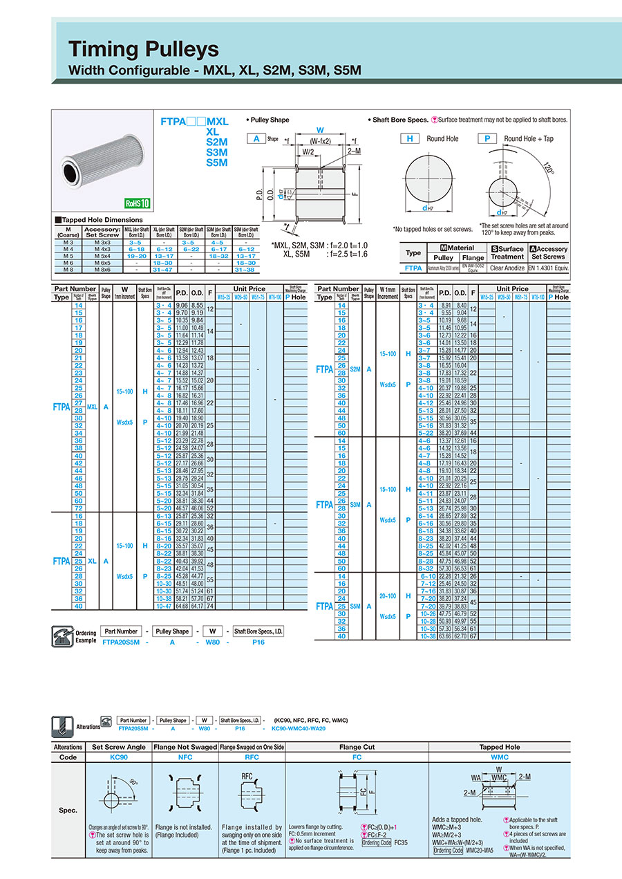
Timing belt pulleys / profile selectable / flanged pulley deselectable / aluminium

Cuidado
- Please note that the swaged flange options, NFC, RFC, and LFC, are not reflected in the CAD data.
Número da peça:
candidatos encontrados.Desenho de contorno e tabela de especificações
* For XL type and S5M type, the flange thickness is 1.5.
FTPA□□MXL
XL
S2M
S3M
S5M
Shape A
H round hole
P Round Hole + Tap
* MXL, S2M, S3M: f = 2.0 t = 1.0
XL, S5M: f = 2.5 t = 1.5

[ ! ] Surface treatment may not be applied to the shaft bores.
[ ! ] Unless otherwise specified except for teeth and F dimensions, the dimension tolerance conforms to JIS B 0405 Class m.
| M (Coarse) | Accessory Set Screws | MXL (dH7 Shaft Bore I.D.) | XL (dH7 Shaft Bore I.D.) | S2M (dH7 Shaft Bore I.D.) | S3M (dH7 Shaft Bore I.D.) | S5M (dH7 Shaft Bore I.D.) |
| M 3 | M 3 × 3 | 3 to 5 | — | 3 to 5 | 4 to 5 | — |
| M 4 | M 4 × 3 | 6 to 18 | 6 to 12 | 6 to 22 | 6 to 17 | 6 to 12 |
| M 5 | M 5 × 4 | 19 to 20 | 13 to 17 | — | 18 to 32 | 13 to 17 |
| M 6 | M 6 × 5 | — | 18 to 30 | — | — | 18 to 30 |
| M 8 | M 8 × 6 | — | 31 to 47 | — | — | 31 to 38 |
| Type | [M] Material | [S] Surface Treatment | [A] Accessory Set Screws | |
| Pulley | Flange | |||
| FTPA | 2000 Series Aluminum Alloy | Aluminum alloy | Clear Anodize | EN 1.4301 Equiv. |
Specification Table
| Part number | — | Pulley Shape | — | W | — | Shaft Bore Specs.: I.D. |
| FTPA20S5M | — | A | — | W80 | — | P16 |
| Part number | Pulley Shape | W 1 mm Increments | Shaft Bore Specifications | Shaft Bore Dia.dH7 (1 mm Increments) | P.D. | O.D. | F | ||
| Type | Number of Teeth | Belt Type | |||||||
| FTPA | 14 | MXL | A | 15 to 100 W ≤ d × 5 | H P | 3· 4 | 9.06 | 8.55 | 12 |
| 15 | 3· 4 | 9.70 | 9.19 | ||||||
| 16 | 3 to 5 | 10.35 | 9.84 | 14 | |||||
| 17 | 3 to 5 | 11.00 | 10.49 | ||||||
| 18 | 3 to 5 | 11.64 | 11.14 | ||||||
| 19 | 3 to 5 | 12.29 | 11.78 | ||||||
| 20 | 4 to 6 | 12.94 | 12.43 | 18 | |||||
| 21 | 4 to 6 | 13.58 | 13.07 | ||||||
| 22 | 4 to 6 | 14.23 | 13.72 | ||||||
| 23 | 4 to 7 | 14.88 | 14.37 | 20 | |||||
| 24 | 4 to 7 | 15.52 | 15.02 | ||||||
| 25 | 4 to 7 | 16.17 | 15.66 | ||||||
| 26 | 4 to 8 | 16.82 | 16.31 | 22 | |||||
| 27 | 4 to 8 | 17.46 | 16.96 | ||||||
| 28 | 4 to 8 | 18.11 | 17.60 | ||||||
| 30 | 4 to 10 | 19.40 | 18.90 | 25 | |||||
| 32 | 4 to 10 | 20.70 | 20.19 | ||||||
| 34 | 4 to 10 | 21.99 | 21.48 | ||||||
| 36 | 5 to 12 | 23.29 | 22.78 | 28 | |||||
| 38 | 5 to 12 | 24.58 | 24.07 | ||||||
| 40 | 5 to 12 | 25.87 | 25.36 | 30 | |||||
| 42 | 5 to 12 | 27.17 | 26.66 | ||||||
| 44 | 5 to 13 | 28.46 | 27.95 | 32 | |||||
| 46 | 5 to 13 | 29.75 | 29.24 | ||||||
| 48 | 5 to 15 | 31.05 | 30.54 | 35 | |||||
| 50 | 5 to 15 | 32.34 | 31.84 | ||||||
| 60 | 5 to 20 | 38.81 | 38.30 | 44 | |||||
| 72 | 5 to 20 | 46.57 | 46.06 | 52 | |||||
| FTPA | 16 | XL | A | 15 to 100 W ≤ d × 5 | H P | 6 to 13 | 25.87 | 25.36 | 32 |
| 18 | 6 to 15 | 29.11 | 28.60 | 36 | |||||
| 19 | 6 to 15 | 30.72 | 30.22 | ||||||
| 20 | 8 to 16 | 32.34 | 31.83 | 40 | |||||
| 22 | 8 to 20 | 35.57 | 35.07 | 45 | |||||
| 24 | 8 to 22 | 38.81 | 38.30 | ||||||
| 25 | 8 to 22 | 40.43 | 39.92 | 48 | |||||
| 26 | 8 to 23 | 42.04 | 41.53 | ||||||
| 28 | 8 to 25 | 45.28 | 44.77 | 55 | |||||
| 30 | 10 to 30 | 48.51 | 48.00 | ||||||
| 32 | 10 to 30 | 51.74 | 51.24 | 61 | |||||
| 36 | 10 to 38 | 58.21 | 57.70 | 67 | |||||
| 40 | 10 to 47 | 64.68 | 64.17 | 74 | |||||
| Part number | Pulley Shape | W 1 mm Increments | Shaft Bore Specifications | Shaft Bore Dia.dH7 (1 mm Increments) | P.D. | O.D. | F | ||
| Type | Number of Teeth | Belt Type | |||||||
| FTPA | 14 | S2M | A | 15 to 100 W ≤ d × 5 | H P | 3· 4 | 8.91 | 8.40 | 12 |
| 15 | 3· 4 | 9.55 | 9.04 | ||||||
| 16 | 3 to 5 | 10.19 | 9.68 | 14 | |||||
| 18 | 3 to 5 | 11.46 | 10.95 | ||||||
| 20 | 3 to 6 | 12.73 | 12.22 | 16 | |||||
| 22 | 3 to 6 | 14.01 | 13.50 | 18 | |||||
| 24 | 3 to 7 | 15.28 | 14.77 | 20 | |||||
| 25 | 3 to 7 | 15.92 | 15.41 | 20 | |||||
| 26 | 3 to 8 | 16.55 | 16.04 | 22 | |||||
| 28 | 3 to 8 | 17.83 | 17.32 | ||||||
| 30 | 3 to 8 | 19.01 | 18.59 | ||||||
| 32 | 4 to 10 | 20.37 | 19.86 | 25 | |||||
| 36 | 4 to 10 | 22.92 | 22.41 | 28 | |||||
| 40 | 4 to 12 | 25.46 | 24.96 | 30 | |||||
| 44 | 5 to 13 | 28.01 | 27.50 | 32 | |||||
| 48 | 5 to 15 | 30.56 | 30.05 | 35 | |||||
| 50 | 5 to 16 | 31.83 | 31.32 | ||||||
| 60 | 5 to 22 | 38.20 | 37.69 | 44 | |||||
| FTPA | 14 | S3M | A | 15 to 100 W ≤ d × 5 | H P | 4 to 6 | 13.37 | 12.61 | 16 |
| 15 | 4 to 6 | 14.32 | 13.56 | 18 | |||||
| 16 | 4 to 7 | 15.28 | 14.52 | ||||||
| 18 | 4 to 8 | 17.19 | 16.43 | 20 | |||||
| 20 | 4 to 8 | 19.10 | 18.34 | 22 | |||||
| 22 | 4 to 10 | 21.01 | 20.25 | 25 | |||||
| 24 | 4 to 10 | 22.92 | 22.16 | ||||||
| 25 | 4 to 11 | 23.87 | 23.11 | 28 | |||||
| 26 | 5 to 11 | 24.83 | 24.07 | ||||||
| 28 | 5 to 13 | 26.74 | 25.98 | 30 | |||||
| 30 | 6 to 14 | 28.65 | 27.89 | 32 | |||||
| 32 | 6 to 16 | 30.56 | 29.80 | 35 | |||||
| 36 | 6 to 18 | 34.38 | 33.62 | 40 | |||||
| 40 | 8 to 23 | 38.20 | 37.44 | 44 | |||||
| 44 | 8 to 25 | 42.02 | 41.25 | 48 | |||||
| 48 | 8 to 25 | 45.84 | 45.07 | 50 | |||||
| 50 | 8 to 28 | 47.75 | 46.98 | 52 | |||||
| 60 | 8 to 32 | 57.30 | 56.53 | 61 | |||||
| FTPA | 14 | S5M | A | 20 to 100 W ≤ d × 5 | H P | 6 to 10 | 22.28 | 21.32 | 26 |
| 16 | 7 to 12 | 25.46 | 24.50 | 32 | |||||
| 20 | 7 to 16 | 31.83 | 30.87 | 36 | |||||
| 24 | 7 to 20 | 38.20 | 37.24 | 45 | |||||
| 25 | 7 to 20 | 39.79 | 38.83 | ||||||
| 30 | 10 to 26 | 47.75 | 46.79 | 52 | |||||
| 32 | 10 to 28 | 50.93 | 49.97 | 55 | |||||
| 36 | 10 to 30 | 57.30 | 56.34 | 61 | |||||
| 40 | 10 to 38 | 63.66 | 62.70 | 67 | |||||
Alterations
| Part number | — | Pulley Shape | — | W | — | Shaft Bore Specs.: I.D. | — | (KC90·NFC·RFC·FC·WMC) |
| FTPA20S5M | — | A | — | W80 | — | P16 | — | KC90 − WMC40 − WA20 |
| Alterations | Set Screw Angle Change | No Flange | Single Flange | Flange Cut | Tapped Hole | ||
| Code | KC90 | NFC | RFC | FC | WMC | ||
| Spec. |  |  |  |  |  | ||
Changes an angle of set screw to 90°. [ ! ] The set screw hole is set at around 90° to keep away from peaks. | The product is shipped without swaging the flange. (Flange Included) | The product is shipped with the flange swaged only on one side. (Flange 1 pc. Included) | Lowers the flange by cutting. FC: 0.5 mm Increments [ ! ] No surface treatment is applied on flange circumference. | [ ! ]FC ≥ (O. D.) +1 [ ! ]FC ≤ F-2 Ordering Code FC35 | Adds a tapped hole. WMC ≥ M+3 WA ≥ M/2+3 WMC+WA ≤ W- (M/2+3) Ordering Code WMC20-WA5 | [ ! ] Applicable to the shaft bore specs. P. [ ! ] 4 pieces of set screws are included [ ! ] If WA is not specified, WA = (W-WMC)/2. | |
Lista de números de peça
| Número da peça |
|---|
Preço unitário (excluindo IVA)(Preço unitário incluindo IVA) | Data de envio standard |
|---|
- ( - ) | 6 dias úteis |
- ( - ) | 6 dias úteis |
- ( - ) | 6 dias úteis |
- ( - ) | 6 dias úteis |
- ( - ) | 6 dias úteis |
- ( - ) | 6 dias úteis |
- ( - ) | 6 dias úteis |
- ( - ) | 6 dias úteis |
- ( - ) | 6 dias úteis |
- ( - ) | 6 dias úteis |
- ( - ) | 6 dias úteis |
- ( - ) | 6 dias úteis |
- ( - ) | 6 dias úteis |
- ( - ) | 6 dias úteis |
- ( - ) | 6 dias úteis |
- ( - ) | 6 dias úteis |
- ( - ) | 6 dias úteis |
- ( - ) | 6 dias úteis |
- ( - ) | 6 dias úteis |
- ( - ) | 6 dias úteis |
- ( - ) | 9 dias úteis |
- ( - ) | 9 dias úteis |
- ( - ) | 9 dias úteis |
- ( - ) | 9 dias úteis |
- ( - ) | 9 dias úteis |
- ( - ) | 6 dias úteis |
- ( - ) | 6 dias úteis |
- ( - ) | 6 dias úteis |
- ( - ) | 6 dias úteis |
- ( - ) | 6 dias úteis |
- ( - ) | 6 dias úteis |
- ( - ) | 6 dias úteis |
- ( - ) | 6 dias úteis |
- ( - ) | 9 dias úteis |
- ( - ) | 9 dias úteis |
- ( - ) | 9 dias úteis |
- ( - ) | 6 dias úteis |
- ( - ) | 6 dias úteis |
- ( - ) | 9 dias úteis |
- ( - ) | 9 dias úteis |
- ( - ) | 9 dias úteis |
- ( - ) | 6 dias úteis |
- ( - ) | 6 dias úteis |
- ( - ) | 6 dias úteis |
- ( - ) | 6 dias úteis |
- ( - ) | 6 dias úteis |
- ( - ) | 6 dias úteis |
- ( - ) | 9 dias úteis |
- ( - ) | 9 dias úteis |
- ( - ) | 9 dias úteis |
- ( - ) | 9 dias úteis |
- ( - ) | 6 dias úteis |
- ( - ) | 6 dias úteis |
- ( - ) | 6 dias úteis |
- ( - ) | 6 dias úteis |
- ( - ) | 6 dias úteis |
- ( - ) | 6 dias úteis |
- ( - ) | 6 dias úteis |
- ( - ) | 6 dias úteis |
- ( - ) | 6 dias úteis |
Informações detalhadas
Informações básicas
Cuidado
- Please note that the swaged flange options, NFC, RFC, and LFC, are not reflected in the CAD data.
Contorno e especificações
General Information - Toothed Pulleys/Timing Pulleys/Idler Pulleys
Selection details of toothed pulleys/timing pulleys/idler pulleys
- Material: aluminum, steel, stainless steel (stainless steel), plastic
- Coatings: uncoated, burnished, anodized, nickel-plated
- Profile form: 1.5GT, 2GT, 3GT, 5GT, P2M, P3M, P5M, P8M, S2M, S3M, S5M, S8M, S14M, T2.5, T5, T10, AT5, AT10, 5M, 8M, 14M, 8YU, H, L, MXL, XL, PowerGrip GT3: MR2, MR3, MR5
- ISO tolerances: H7
- Belt width (mm): 4, 4.8, 6, 6.4, 7, 7.9, 9, 9.5, 10, 12, 12.7, 15, 18, 19.1, 20, 25, 25.4, 26, 28, 30, 31, 38,1, 40, 50, 50.8, 53, 60, 74, 76.2, 100
- Belt width (inches): 0.19, 0.25, 0.31, 0.37, 0.5, 0.75, 1, 1.5, 2
- Number of teeth: 10 to 72
Description/Basics
The toothed pulley for mechanical engineering is intended for the transmission of force and torque. Timing pulleys enable a gear ratio of speeds through belt pulleys of different sizes. Timing pulleys are more efficient, durable and significantly more maintenance-friendly compared to chain transmissions.
How much torque and load a timing pulley can transmit depends on the width of the belt. The width of the belt must be calculated. It is recommended to ensure the belt is correctly tensioned. MISUMI already offers the suitable idler pulley and return rollers with integrated ball bearings. For design and design help follow this link.
Different profile shapes of the toothed belts and belt pulleys are responsible for the transmission of power. Depending on the positioning accuracy, the applied torque and the conveying weight, MISUMI offers the fitting pulley. Toothed belt drives are generally used in the industry in three areas:
Positioning: Timing pulleys is often used in 3D printers. A toothed pulley with a semi-circular profile (e.g., GT) is often used for the required position accuracy of a 3D printers. The round shape offers the benefit of little play when the direction changes.
Drive: toothed pulleys are also used for high torque. In most cases, a timing pulley with a rounded trapezoidal profile (e.g., S8M) is used. These are particularly well suited for the transmission of high forces, which occur in drives of various applications in order to drive mechanical components.
Conveying: toothed pulleys can also be used for transporting loads. A straight trapezoidal profile is often used for this purpose (e.g., AT). This toothed pulley shape offers a large surface for loading and transmitting of loads.
Which toothed pulley or timing pulley is the right one for your application depends on the respective task of the toothed belt drive. Different toothed disc profiles have proven themselves for each type of application.
Various bore hole shapes and fastening variants are available for shaft mounting. These allow fastening via set screws, keyways and by means of Mecha locks. Fastening via a clamping sleeve has the further advantage that it allows adjusting the alignment continuously. The MISUMI product assortment has these ready-to-install.
Application Examples - Toothed Pulleys/Timing Pulleys/Idler Pulleys

Application example: idler pulley
(1) Idler pulleys, (2) chain tensioner
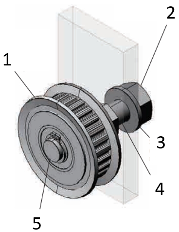
Application example: deflection roller
S (1) Toothed pulleys with crimp disc, (2) nut, (3) washer, (4) cantilever shaft, (5) retaining ring

Application example: timing pulleys
(1) Flat head screw, (2) Timing pulley, (3) Timing belt, (4) Screw-on terminal
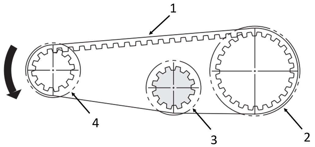
Application example: of toothed belt drives
(1) Toothed belt, (2) driven toothed pulley with crimp disc, (3) idler pulley with crimp disc, (4) driving toothed pulley with crimp disc
Industrial Applications