● Dynamic / DK connectors are compact nylon connectors developed especially for industrial equipment. With strengthened housing and contacts compared to conventional products, and a wide selection of housing types, these connectors are especially suited for use with FA equipment.
● Dynamic / DK connectors are suitable for both power supply and signal use.
● 3100 series with rated 250 V, 3200 series with rated 600 V, and 5200 series with rated 630 V available.
● The Dynamic Series and DK series are compatible connectors.
Confirmado
- Compatible Wire AWG Size
- 20
- Contact Shape
- Compatible Connector
- Cable Length(m)
- 5
- Dias de envio estimados
- Tudo
- Dentro de 7 dias úteis
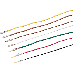
Dynamic Connector Crimped Contact Cable (D3100 / D3200 Series)【50 unidades】 (175217-20-C-5)
Especificações do produto
Specifications

1 Pack Unit With Total of 50
| Model Number | Contact Type | Cable Color Specified | Parts Specification | Weight 1 m | |||
| Stock (1 m) Non-stock (2 m ~) | Non-stock | Used Cable | Used Contact Model Number | ||||
| (g) | |||||||
| 175218-16 | Female (Socket) | B (Blue) C (White) D (Black) | A (Brown) E (Red) F (Yellow) G (Green) | AWG16 | UL1007 Type | 175218-2 | 882 |
| 175217-20 | AWG20 | 175217-2 | 417 | ||||
| 175216-24 | AWG24 | 175216-2 | 231 | ||||
| 175289-16 | Male (Pin) | AWG16 | 175289-2 | 882 | |||
| 175288-20 | AWG20 | 175288-2 | 416 | ||||
| 175287-24 | AWG24 | 175287-2 | 231 | ||||
More Information

Informações detalhadas
Informações básicas
No special tools required. Ideal for field assembly with quick delivery. 1 package contains 50 pieces

● Sold as a pack of crimped cables.
● High Quality Crimped Connector Cables Processed at a Misumi Factory
● Connector cables can be assembled without investing in specialized tools.
● Available as 50 pieces / pack

· If the wiring is incorrect, remove it with the dedicated wire removal tool.
· To reuse, raise the contact lance.
Especificações comuns
Dynamic / DK
Features
Common Specifications

● Uses the housing lance method
Fixing after the contact housing is installed commonly uses a locking method in which a lance on the contact side is latched on to the housing. These connectors instead use a housing lance method in which a lance is located on the housing. Because there is no lance on the contact, contacts will not become tangled during operation or storage, and issues such as the lance becoming deformed are eliminated. Consequently, insertion into the housing is easier, and secure connections are possible without the wires becoming disconnected. A locking sound when properly inserted notifies of a secure connection. Easy removal using a dedicated removal tool.
Fixing after the contact housing is installed commonly uses a locking method in which a lance on the contact side is latched on to the housing. These connectors instead use a housing lance method in which a lance is located on the housing. Because there is no lance on the contact, contacts will not become tangled during operation or storage, and issues such as the lance becoming deformed are eliminated. Consequently, insertion into the housing is easier, and secure connections are possible without the wires becoming disconnected. A locking sound when properly inserted notifies of a secure connection. Easy removal using a dedicated removal tool.

Design includes prying prevention structure
Both male (pin) (including circuit board connectors) and female (socket) connectors are ribbed (convex/concave) and interlock making them highly resistant to prying. Product features a built-in safety design - the male (pin) and female (socket) must be perfectly inserted with no looseness between the housing for contacts to connect.
● About contact pressure
Contact pressure is divided into high pressure and standard pressure based on the sub-beam position. Misumi standard inventory consists of gold-plated standard contact pressure models.
Contact pressure is divided into high pressure and standard pressure based on the sub-beam position. Misumi standard inventory consists of gold-plated standard contact pressure models.
| Plating | Contact Pressure Type | Contact Pressure | Use | Number of Insertions / Removals |
|---|---|---|---|---|
| Gold | Standard Contact Pressure | Approx. 150 g | For multi-core circuits with frequent insertions / removals used for signal / power supply | 500 times |
| High Contact Pressure | Approx. 250 g | For signal, power supply, and motor applications with large vibration | 500 times | |
| Tin | High Contact Pressure | Approx. 400 g | For signal and power supply applications with less frequent insertions / removals | 100 times |
● Advantages of Gold-Plated Contacts
Choice of gold or silver plated contacts will depend on operational factors such as voltage, current, environment (vibration, temperature, gases, etc.), core numbers, etc.
In general, gold plating is recommended for industrial devices.
Choice of gold or silver plated contacts will depend on operational factors such as voltage, current, environment (vibration, temperature, gases, etc.), core numbers, etc.
In general, gold plating is recommended for industrial devices.
Plating Type and Electrical Capacity
| Gold Plate | Undetermined Zone | Tin-plated | Not Plated (Reference) | |
|---|---|---|---|---|
| Voltage | 3 V or less | 3 ~ 30 V | 30 ~ 100 V | 100V or more |
| Current | 1 A or less | 1 ~ 10 A | 1 ~ 10 A | 0.1A or more |
As shown on the table listed above, gold plating must be used for conditions of 3 V ,1 A and below. Tin plated products may be used for 30 V, 1 A or higher applications. While tin plated products are appropriate for Clean Environments, please use gold-plated products for unfavorable environmental conditions such as high temperature/humidity, various gases, high vibration, frequent insertion/removal etc.
● Use of Tab / Recessed Contact Method
Use of the plate tab style on the male side and recessed style (to receive the flat plate) on the receiving female side improves the prying resistance of the structure. 3 point contact method provides highly reliable connections.
Use of the plate tab style on the male side and recessed style (to receive the flat plate) on the receiving female side improves the prying resistance of the structure. 3 point contact method provides highly reliable connections.

Easy insertion and removal
Simply insert the connector to plug it in. There will be an audible locking sound when it is properly inserted. In addition there is a fitting confirmation line that can also be used to check for proper fit. Pinch the 2 lock levers on both sides of the housing for easy removal.

Common Specifications (3100 and 3200 Series)
Material / Finish
Simply insert the connector to plug it in. There will be an audible locking sound when it is properly inserted. In addition there is a fitting confirmation line that can also be used to check for proper fit. Pinch the 2 lock levers on both sides of the housing for easy removal.| Type | Material | Finish |
|---|---|---|
| Female Contact | Copper Alloy | Gloss Tin-Plating and Gold Plating Over Nickel Base |
| Male Contact | ||
| Housing | UL94V-0, Polyester with Glass Fiber Reinforcement (PBT), PPS (SMT type), Black | |
Compatible Wire Size
| AWG | Conductor Section Area mm2 | |
|---|---|---|
| Size | 28 ~ 16 | 0.08 ~ 1.25 |
Specifications
| Item | D3100 Series | D3200 Series |
|---|---|---|
| Rated Voltage | 250 VAC / VDC or less | 600 VAC / VDC or less |
| Rated Current* | 1-core: 12A | |
| 3-core: 15 A | ||
| 6-core: 10A | ||
| 16-core: 8A | ||
| (Used with AWG16 wires) | ||
| Withstand Voltage | 1,500 VAC / minute | 2,200 VAC / minute |
| Contact Resistance | 10 mΩ or less | |
| Operating Temperature Range | -55°C ~ +105°C | |
| Insulation Resistance | 1,000 MΩ or higher | |
| Insertion / Removal Force (per core) | Insertion: 500 g or less. Removal: 30 g or more | |
| Contact Retention Force | 49N or more | |
| Temperature Rise (Rated Conditions) | 30°C or less | |
| Durability | Contact resistance at 10 mΩ or less after 500 trials (100 mm/min.) of insertions and removals | |
* Rated current value indicates the current value per core. Consequently, a 6 core connector can handle a current of 60 A. However, please be aware that rated current value per core will decline as the number of cores increases. If you don't see your desired core count on the chart to the left, please use the current curve below for reference.
Rating
| Specifications / Series | 3100 Series (3.81 mm pitch) | 3200 Series (5.08 mm pitch) | ||||||||||||||||||||||||||||||||||||||||
|---|---|---|---|---|---|---|---|---|---|---|---|---|---|---|---|---|---|---|---|---|---|---|---|---|---|---|---|---|---|---|---|---|---|---|---|---|---|---|---|---|---|---|
| Rated Voltage | Rated Current | Rated Temperature | Rated Voltage | Rated Current | Rated Temperature | |||||||||||||||||||||||||||||||||||||
| AMP Standard 108-5349 |
250 V | (See table below) | -55°C ~ +105°C | 600 V (single connector use) |
(See table below) | -55°C ~ +105°C | ||||||||||||||||||||||||||||||||||||
| UL File No.E28476 (Recognized Component) |
Determined by conditions specific to the device in use |
Determined by conditions specific to the device in use |
- | Determined by conditions specific to the device in use |
Determined by conditions specific to the device in use |
- | ||||||||||||||||||||||||||||||||||||
| CSA Report No. LR7189 |
250 V | 8 A, max. | - | 250 V | 8 A, max. | - | ||||||||||||||||||||||||||||||||||||
| TÜV License No. R9151488 (VDE0627) IP Protection, IP-00 Overvoltage Category (II) Repeated Insertion/ Removal: 50 times |
250 V |
|
-20°C ~ +105°C | 500 V |
|
-20°C ~ +105°C | ||||||||||||||||||||||||||||||||||||

Common Specifications (5200 Series)
Specifications
| Rated Voltage | 630 VAC / VDC |
|---|---|
| Rated Current | 30 A max. (Refer to Table A) |
| Withstand Voltage | 3,000 VAC (1 minute) |
| Insulation Resistance | 1,000 MΩ or higher |
| Contact Resistance | 2 mΩ or less |
| Applicable Electric Wire Range | AWG16 ~ 10 (1.23 ~ 5.50 mm2) |
| Suitable Electric Wire Insulation Coating Outer Diameter | 3.0 ~ 5.2 mm |
| Operating Temperature Range | -55 ~ +105°C |
| Compatible Panel Thickness | 1.6 ~ 2.4 mm ±0.1 |
| Used Wire Size (AWG) | 10 | 12 | 14 | 16 |
|---|---|---|---|---|
| Current (Ampere) | 30 | 25 | 19 | 16 |
Material / Finish
| Type | Material | Finish |
|---|---|---|
| Female Contact | Copper Alloy | Gold plated over nickel base coat and silver plated over nickel base coat |
| Male Contact | ||
| Housing | UL94V-0, polyester with glass fiber reinforcement (PBT), black | |
[Compatibility Table]
| 3100 Series | |
|---|---|
| D3100 | DK3100 |
| 1-178288-3-20P | MDK-3100S-03R-20P |
| 1-178288-5-20P | MDK-3100S-05R-20P |
| 178289-3-20P | MDK-3100D-06R-20P |
| 178289-5-20P | MDK-3100D-10R-20P |
| 1-177648-3-20P | MDK-3100S-03F-20P |
| 1-177648-5-20P | MDK-3100S-05F-20P |
| 178964-3-20P | MDK-3100D-06F-20P |
| 178964-5-20P | MDK-3100D-10F-20P |
| 1-178802-3-20P | MDK-3100S-03P-20P |
| 1-178802-5-20P | MDK-3100S-05P-20P |
| 178803-3-20P | MDK-3100D-06P-20P |
| 178803-5-20P | MDK-3100D-10P-20P |
| 3200 Series | |
| D3200 | DK3200 |
| 1-178128-2-20P | MDK-3200S-02R-20P |
| 1-178128-3-20P | MDK-3200S-03R-20P |
| 1-178128-4-20P | MDK-3200S-04R-20P |
| 1-179552-2-20P | MDK-3200S-02F-20P |
| 1-179552-3-20P | MDK-3200S-03F-20P |
| 1-179552-4-20P | MDK-3200S-04F-20P |
| 1-179553-2-20P | MDK-3200S-02P-20P |
| 1-179553-3-20P | MDK-3200S-03P-20P |
| 1-179553-4-20P | MDK-3200S-04P-20P |
| 5200 Series | |
|---|---|
| D5200 | DK5200 |
| 1-179958-2-10P | MDK-5200S-02R-10P |
| 1-179958-3-10P | MDK-5200S-03R-10P |
| 1-353046-2-10P | MDK-5200S-02F-10P |
| 1-353046-3-10P | MDK-5200S-03F-10P |
| 5200 Contact | |
|---|---|
| D5200 | DK5200 |
| 917804-2 | MDK-5TABSLP1-100P |
| 316040-2 | MDK-5RECSLP1-100P |
| 917805-2 | MDK-5TABMLP1-100P |
| 316041-2 | MDK-5RECMLP1-100P |
| 3100 / 3200 Common Contact | |
|---|---|
| D3100 / D3200 | DK3100 / DK3200 |
| 175287-2 | MDK-3TABSLP1-100P |
| 175288-2 | MDK-3TABMLP1-100P |
| 175289-2 | MDK-3TABLLP1-100P |
| 175216-2 | MDK-3RECSLP1-100P |
| 175217-2 | MDK-3RECMLP1-100P |
| 175218-2 | MDK-3RECLLP1-100P |
O número da peça foi confirmado