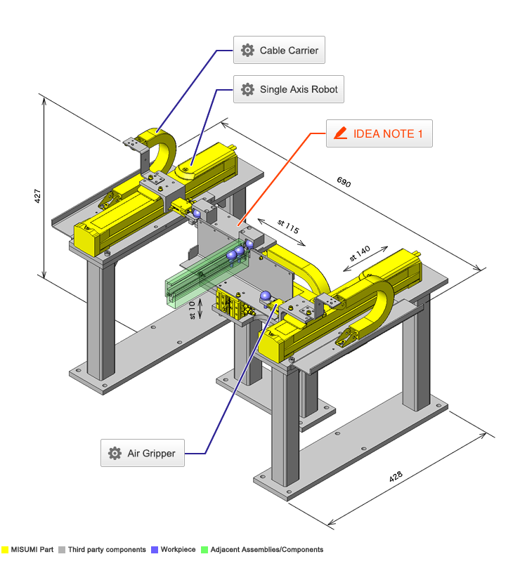
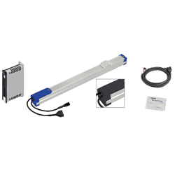
Single Axis Robot
* Orange colored cells in the table below indicate the part numbers used in this example.
Selection criteria
Robot is selected to minimize jerk during transporting.
Back to page top
Available sizes
■Single axis robot (RS, slider type, No brake)
■General specifications
| Ball screw | Motor | Position detector | Operating environment
temp - Humidity | Controller input
power supply |
Ø8
(C10 Rolled) | Stepping | Resolver
(Incremental) | 0 ~ 40°C ・ 35 ~ 85%RH
(No condensation) | DC24V±10% |
Ø12
(C10 Rolled) |
Basic specifications
Slider Upper Surface
Height (mm) | Type | Lead
(mm) | Stroke
(mm) |
| 51 | RS1 | 2 | 50 ~ 400
(Increment of 50) |
| 6 |
| 12 |
| 57 | RS2 | 6 | 50 ~ 800
(Increment of 50) |
| 12 |
| 20 |
| 60 | RS3 | 6 | 50 ~ 800
(Increment of 50) |
| 12 |
| 20 |
Back to page top
Selection steps
■Single axis robot selection steps
Load capacity
↓
Stroke
↓
Cycle time or Max. Speed
↓
Detail confirmation
Back to page top
Accuracy Info
■Single axis robot accuracy
Repeatability: ±0.02
Back to page top
Performance info.
■Single axis robot Performance info.
Slider Upper Surface
Height (mm) | Type | Lead
(mm) | Load capacity (kg) | Max. push force | Allowable moment capacity (N・m) | Max speed
(mm/sec) | Rated
life |
| Horizontal | Vertical | (N) | Pitching | Yawing | Rolling |
| 51 | RS1 | 2 | 6 | 4 | 150 | 19 | 16 | 17 | 100 | 10,000km
or more |
| 6 | 4 | 2 | 90 | 300 |
| 12 | 2 | 1 | 45 | 600 |
| 57 | RS2 | 6 | 10 | 2 | 90 | 33 | 25 | 30 | 300 ~ 190 | 10,000km
or more |
| 12 | 6 | 1 | 45 | 600 ~ 380 |
| 20 | 4 | - | 27 | 1000 ~ 633 |
| 60 | RS3 | 6 | 12 | 4 | 120 | 38 | 32 | 34 | 300 ~ 190 | 10,000km
or more |
| 12 | 8 | 2 | 60 | 600 ~ 380 |
| 20 | 6 | - | 36 | 1000 ~ 633 |
Back to page top
Air Gripper
| Product name | Air Gripper/Parallel Type |
| Part number | ACHK6-N |
| Features | Compact Type Pneumatic Grippers with high precision, high rigidity, strong retaining force and. |
* Orange colored cells in the table below indicate the part numbers used in this example.
Selection criteria
Compact suitable for workpiece gripping.
Back to page top
Available sizes
■Small parallel air gripper (Integrated sensor)
| Part name | Material | Surface treatment |
| Main body | EN AW-5056 Equiv. | Clear anodize |
| Fingers ・ Attachment mount | EN 1.1191 Equiv. | Nitriding treatment |
■Specifications and Dimensions
| Operating method | Stroke | Cylinder I.D. | Overall width | Overall height | Thickness |
| Single Acting ・ Double Acting | 4 | Ø8 | 26 | 40.5 | 10 |
| 6 | Ø12 | 30 | 45 | 16.4 |
Back to page top
Selection steps
■Small parallel gripper selection steps
- Confirmation of Conditions
- (Confirming required stroke,weight, and shape)
↓
- Calculation of required gripping force
-
- 10 ~ 20 times of the workpiece weight required
- (Varies by friction coefficient of fingers and workpiece.)
↓
- Model Selection
-
- ●Gripping method (O.D. gripping ・ I.D. gripping)
- ●Open/close operation method (Single acting or Dual acting)
- ●Stroke
- ●Gripping points and gripping force
Back to page top
Performance info.
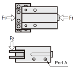
■Small parallel gripper (Integrated sensor) load info.
| Stroke | Cylinder
I.D. | Operating pressure
range | Effective gripping force (N) | Allowable static load (N) |
| Single acting (Spring) | Dual acting | F1 | F2 |
| 4 | Ø8 | 0.3 ~ 0.5MPa | 4.2 (1) | 4.9 | 5 | 2.5 |
| 6 | Ø12 | 10.4 (1.9) | 12.2 | 10 | 5 |
Back to page top
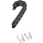
Cable Carrier
| Product name | Cable Carriers/Flap Open-Close Type (Cable Carrier+Mounting Brackets) |
| Part number | MHPUS202-45-12-A |
* Orange colored cells in the table below indicate the part numbers used in this example.
Selection criteria
To protect connection cables
Back to page top
Available sizes
■Cable carrier, Flap open/close type
| Main body | Mounting bracket |
| Material | Material | Surface treatment |
Nylon 6 + Glass Fiber 20%
(Operating temp. -10 ~ 80°C)
Flammability standards UL94-HB equivalent | Low Carbon Steel | Trivalent chromate |
■Sizes and Dimensions
Name
No. | Bend radius | Number of links | Mounting direction | Inner height | Mounting height | (Required
space
height) |
| Inner height | Height | Inner width | Width | Link pitch |
| 102 | 19 | 5 ~ 23 | Mounting Direction S | 9 | 12 | 20 | 27 | 20 | 50 | 65 |
| 202 | 25 | 6 ~ 34 | For Moving Ends: Mounting on the Outer Circumference
For Both Moving and Fixed Ends: Common to the outer and inner circumferences | For Moving Ends: Mounting on the Inner Circumference
For Both Moving and Fixed Ends: Common to the outer and inner circumferences | 14 | 20 | 14 | 26 | 25 | 70 | 85 |
| 30 | 6 ~ 34 | 80 | 95 |
| 45 | 8 ~ 36 | 110 | 125 |
| 203 | 30 | 6 ~ 34 | 14 | 20 | 20 | 32 | 25 | 80 | 95 |
| 45 | 8 ~ 36 | 110 | 125 |
| 204 | 38 | 6 ~ 36 | 14 | 22 | 20 | 40 | 32 | 98 | 118 |
| 50 | 7 ~ 37 | 122 | 142 |
| 206 | 38 | 6 ~ 36 | 14 | 22 | 40 | 60 | 32 | 98 | 118 |
| 50 | 7 ~ 37 | 122 | 142 |
| 306 | 50 | 6 ~ 38 | For Moving Ends: Mounting on the Outer Circumference
For Both Moving and Fixed Ends: Common to the outer and inner circumferences | For Moving Ends: Mounting on the Inner Circumference
For Both Moving and Fixed Ends: Common to the outer and inner circumferences | 24 | 34 | 44 | 60 | 45 | 134 | 160 |
| 100 | 10 ~ 42 | 234 | 260 |
| 408 | 50 | 6 ~ 38 | 24.5 | 40 | 58 | 78 | 45 | 140 | 170 |
| 75 | 8 ~ 40 | 190 | 220 |
| 100 | 10 ~ 42 | 240 | 270 |
| 150 | 13 ~ 45 | 340 | 370 |
| 412 | 50 | 6 ~ 38 | 24.5 | 40 | 97 | 117 | 45 | 140 | 170 |
| 75 | 9 ~ 41 | 190 | 220 |
| 100 | 10 ~ 42 | 240 | 270 |
Back to page top
IDEA NOTE Shorten cycle time
The part feeder sorts parts to both the left and right which doubles the feeding capacity and reduces the cycle time.


